HoverTrowel Air Motors
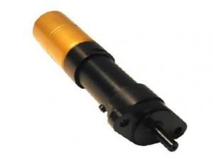
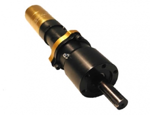
Ingersoll-Rand multi-vane air motors have been selected because of their dependability, low maintenance and excellent design. The motors are compact, lightweight with a high power output. Other features include cool running characteristics that minimize the effects of hot, wet or dusty conditions. Instant starting and stopping eliminates the delays of motor acceleration or deceleration periods, preventing electrostatic sparks and producing safe operation in hazardous conditions. It will not overheat or burn out even when overloaded or run to stall. No hydrocarbon release makes the HoverTrowel ideal for food, beverage and other sensitive industrial areas.
HoverTrowel’s standard motor for common epoxy systems is the HT-167. The higher torque HT-188 is recommended for very resin rich or sticky systems. Other motors are available for some flooring systems with unique physical properties and characteristics. The motors produce a range of rpm and torque loads to suit the needs of most of the polymer toppings on the market today.
HT-167
53 RPM, 78 lb-ft torque
The HT-167 is used for most standard hand and power trowel systems.
HT-188
52 RPM, 128 lb-ft torque
The HT-188 is used for very resin rich systems, as well as the cementatious toppings on the market. This motor will perform well on all systems, making it extremely versatile.
INGERSOLL-RAND AIR POWER ADVANTAGES
- Infinitely variable speeds and torques via pressure regulation or air valves — no costly controls required
- Instant starting, stopping and reversing eliminates the delays of motor speed-up or slow-down periods
- Will not overheat or burn out, even when overloaded or run to stall
- Safe operation in hazardous conditions, with no electrical sparks or hydraulic fluids
- Cool running characteristics minimize the effects of hot, wet or dusty surroundings
- Low maintenance, based on simplicity of design and strength of construction
- Excellent design flexibility — a function of compact size, light weight, and high power output
- Temperature range — up to 150°F with standard lubrication and up to 300°F with high temperature lubrication
Determining Performance Characteristics At Air Pressures Other Than 90 psig
| Air Pressure (psig) | Free Speed (rpm) | Air Consumption at Free Speed (scfm) | Max Power (hp) | Speed at Max Horsepower (rpm) | Torque at Max Horsepower (lb-ft) | Air Consumption at Max Power (scfm) | Stall or Starting Torque (lb-ft) |
|---|---|---|---|---|---|---|---|
| 40 | 80% | 45% | 30% | 80% | 37.5% | 45% | 45% |
| 50 | 84% | 56% | 44% | 84% | 53.4% | 56% | 56% |
| 60 | 88% | 67% | 58% | 88% | 65.9% | 67% | 67% |
| 70 | 92% | 78% | 72% | 92% | 78.3% | 78% | 78% |
| 80 | 96% | 89% | 86% | 96% | 89.6% | 89% | 89% |
| 90 | 100% | 100% | 100% | 100% | 100% | 100% | 100% |
| 100 | 104% | 111% | 114% | 104% | 109.6% | 111% | 111% |
As air pressure changes, the performance characteristics will change by the percentages given above. Example: Knowing the performance characteristics of a Model M004RHR050AR3 reversible ungoverned Air Motor at 90 psig (620 kPa) it is a simple matter to determine its characteristics at another air pressure. Using the percentages from the table for 60 psig (414 kPa), the performance becomes:
| Characteristic | Performance at 90 psig | Percentage Reduction | Performance at 60 psig | ||
|---|---|---|---|---|---|
| Maximum Power (hp) | .41 | x | 58% | = | .24 |
| Free Speed (rpm) | 315 | x | 88% | = | 277 |
| Speed at Max Power (rpm) | 175 | x | 88% | = | 154 |
| Max (Stall) Torque (lb-ft) | 22.1 | x | 67% | = | 14.8 |
| Starting Torque (lb-ft) | 16.5 | x | 67% | = | 11.1 |
| Air Consumption at Free Speed (scfm) | 21.2 | x | 67% | = | 14.2 |
| Air Consumption at Max HP (scfm) | 18.5 | x | 67% | = | 12.4 |
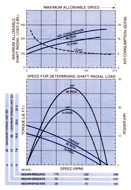
IR Air Motor Performance Curves
Use the performance curves shown to the left for the HoverTrowel’s air motor characteristics. Click the chart to see an enlarged version. Performance data may vary slightly depending on gear ratios; when this occurs, median performance is indicated. Follow the following guidelines for interpreting the performance curves.
Horsepower
- Locate operating speed on the correct horizontal axis of the bottom chart.
- Read Horsepower from the correct curve in the bottom chart.
Torque
- Locate operating speed on the correct horizontal axis of the bottom chart.
- Read Torque from the correct curve in the bottom chart.
Air Compression
- Locate operating speed on the correct horizontal axis on the bottom chart.
- Read Air Consumption from the correct curve in the top chart.
Air Supply or Exhaust Regulation
Reducing or restricting the amount of air supplied to the motor has a similar effect to reducing the air pressure. Choking or restricting the exhaust has a somewhat different effect, with the speed decreasing much more than the torque. The effects of changes in pressure, air supply and exhaust regulation are summarized below. Exact variations in performance with “choked” motors are not tabulated; however, “on the job” tests will usually produce the desired results; sometimes from a combination of pressure adjustments and inlet and exhaust restrictions.
| Air Regulation | Speed | Torque |
|---|---|---|
| Reduced air pressure, or restricting volume of air to motor | Reduced | Greatly Reduced |
| Choking or restricting exhaust | Greatly Reduced | Reduced |


